Research into worm gear wear is going on worldwide which is mainly experimental Hoehn l Octrue 2 Octrue 3 Houser 4 Wang 5. A worm gear drive is used to transmit 22 kW between two shafts which are 225 mm apart.
Agma Worm And Spur Gear Design Equations And Calculators
Design shapes of spur gears 3.
. Whether a worm and wheel gear set will be self-locking depends on frictional contact between the worm and the worm wheel flanks. Px Pitch diameter of the worm. Where n Number of starts of the worm.
DESIGN STEPS CONTINUED 6. Clarify specifications and determine basic elements 2. Equate Ft and FB to find module.
Introduce some of the principles of worm gearing. American Standard Design for Fine-pitch Worm Gearing ANSI B69-1977 This standard is intended as a design procedure for fine-pitch worms and wormgears having axes at right angles. 2 - Speed No of teeth of driven gear If number of teeth in smaller pulley is not given in.
A self-locking worm and wheel gear set can only be driven forward by rotation of the worm. Power speed mG Ka Design factor. Executing the drawings of the parts related to the gears.
N w N G. Worm gears efficiency and wear resistance are normally lower than these of other types of gears of similar size due to high sliding inherently present in worm gear contact. Factory lubricated for life with synthetic semi-.
1 - Speed No of teeth of driving gear 𝑁 2. Speed of the Worm N1 20 RPM. Introduction to Gear Design Introduction Albert Einstein once said.
The worm is threaded screw and worm wheel is toothed gear. The worm can rotate the wheel but worm wheel cannot rotate. Gears Engineering and Design.
Check spur gears strength 4. In Stock Ready to Ship Today. The efficiency of a worm gear ranges from 98 for the lowest ratios to 20 for the highest ratios.
It is the ratio of the speed of worm NW in rpm. The simplest way to obtain a large speed reduction with high torque in a compact space is with worm gear drives. DESIGN PROCEDURE FOR.
The transmission ratio is 241. The tightness of this wrap is tied to the circular spacing of the teeth on the mating gear. Types of Gears Worm gear sets consists of a helical gear and a power screw worm used to transfer motion between non-parallel and non-intersecting shafts.
NW Axial pitch of worm. I are practical and have applications that are very successful. 1This is the general range for most catalog reducers.
Worm gear design parameters. The force of the worm gear mechanism is transmitted by a sliding movement which leads to high operating temperature and low efficiency as well as wear. Worm gearing is not a practical solu-Axlal Movement tion for most applications and other forms of gearing should be.
Rack and Pinion sets a special case of spur gears with the gear having an infinitely large diameter the teeth are laid flat. Worm Gear Boxes Chapter 7 12 Single Worm Gear Boxes 030 030 Rightangle - Gear 20Nm Rating Alluminium RADIAL AND AXIAL LOADS n2 min-1 FA N FR N 1400 20 100 n2 min-1 FA N FR N 200 120 600. A worm drive is a gear arrangement in which a worm which is a gear in the form of a screw meshes with a worm gear which is similar in appearance to a spur gearWorm gears are used to transmit power between two non intersecting non parallel shafts.
Now lets say we have the following design input. 1Calculation of gear ratio From PSGDB page no. To the speed of the worm gear NG in rpm.
The ideal ratio range for worm gear-ing is 5. Nd Tooth system Materials and processes Number of threads on the worm. There are no great advances in gear technology described.
86 𝑖 𝑵. The thread of the screw is basically a long gear tooth wrapped around the axis of rotation. Characteristics and Set-up Worm and mating gear The worm is the input gear that is similar to a screw.
It covers cylindrical worms with helical threads and wormgears hobbed for fully conjugate tooth surfaces. DG Pitch circle diameter of the worm gear. Design the worm gear if it is made of Phosphor bronze 8.
Of threads in worm Px L Nw Normal diametral pitch Axial diametral pitch worm gear helix angle Divide the axial diametral pitch. Things should be made as simple as possible but no simpler This book is an attempt to apply that principle to gear design by presenting information from a manufacturing point-of-view rather than a theoretical one. Worm gears are used when larggge gear reductions are needed.
In other gear types the drive can be given to any one of the two mating parts. This is commonly exploited in a car jack. We will use the term Pitch P for both the pitch in this tutorial.
In this series we explain how to design gears and peripheral parts according to procedures using simple mechanisms. For ratios below 3. Proportions of worm and worm gear 2.
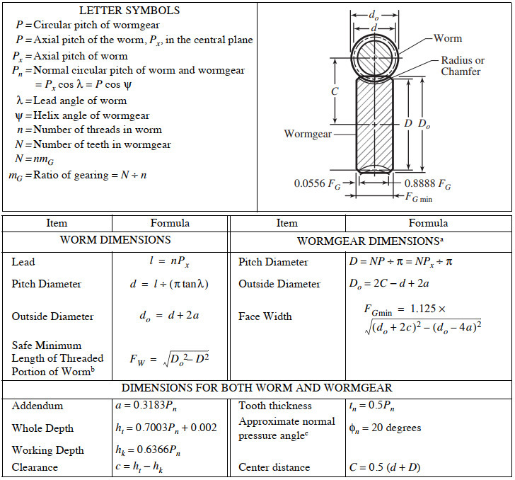
Equations for American Standard Fine Pitch Worms and Wormgears Per. The pitch line velocity is ideally up to 30 ms. 32 Design Procedure for Selection of worm gears - Using PSG Design Data Book Manufactures Catalogue Step.
Worm gears provide a normal single reduction range of 51 to 75-1. 111 Introduction A worm gear is. Also the module of the worm as well as the gear must be equal for a mating worm and gear.
Compare the actual values to the permissible values and repeat process if necessary 14 Determine. Up to 24 cash back CHAPTER 11 Worm Gears Chapter Outline 111 Introduction 439 112 Force Analysis 446 113 AGMA Equations 449 114 Design Procedure 453 115 Conclusions 455 References 456 Further Reading 456 Nomenclature 457 Abstract Worm and wheel gears are widely used for nonparallel nonintersecting right angle gear drive system applications where a. DW Face width of gear.
Bevel and Worm Gears 797 158 Designing a Worm-Gear Mesh A usable decision set for a worm-gear mesh includes Function. But in worm gears the drive is given to only worm. The axial pitch of the worm and the circular pitch of the gear must be same for a mating worm and gear.
It is common for worm gears to have reductions of 201 and even up to 3001 or greater Many worm gears have an interesting property that no other gear set has. The worm wheel teeth envelope the treads on worm which gives line contact between mating parts. Let l Lead of the worm and.
We know that linear velocity of the worm vW l. Such a gear set can therefore be used to hold a load. It does not cover helical gears used as wormgears.
This chapter provides an overview of worms and wheels and outlines a selection procedure. Mathematically velocity ratio VR. No breather or vents to leak.
Design of peripheral structures of gears 5. Ad Shop Online for Binks 31-59 Worm Gear. The worm can easily turn the gear but the gear cannot turn the wormgear but the gear cannot turn the worm.
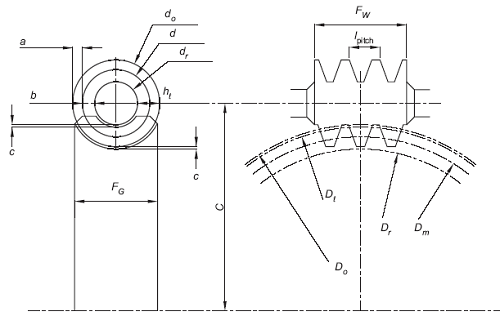
P Circular pitch of wormgear P axial pitch of the worm P x in the central plane P x Axial pitch of worm P n Normal circular pitch of worm and wormgear Px cos λ P cos ψ λ Lead angle of worm ψ Helix angle of wormgear.

Best Worm Gear Design Calculation Pdf

Worm Gear Design Calculation Pdf Merge Peatix
Agma Worm And Spur Gear Design Equations And Calculators
Worm Gearing Classes Proportions Materials And Worm Gear Cutting

Pdf Machine Design Ii Module 2 Gears Lecture 16 Worm Gears Worked Out Problems Contents Aju Joseph Academia Edu

Basic Geometric Calculation For Worm Gears Inventor 2019 Autodesk Knowledge Network
Worm Gears Roy Mech
Surface Durability Of Worm Gear Khk Gears
0 comments
Post a Comment